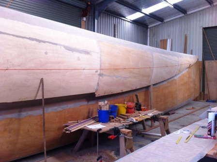
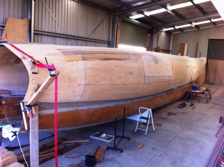
We finally get to see some pictures of Chris Anderson’s cat that he designed and is building. This is going on in New Zealand. North Island I think. This is a CM (cylinder molded) developed plywood vessel. Chris goes away back on the process. In fact he is in the original CM video.
If I may throw in a bit of bio: Chris led the team that designed the fly-by-wire controls for the Boeing 777. I’m surprised he has not also been interviewed by Wolf Blitzer this week.
Being from the antipodes, Chris did not know about Autocad, so he designed and used his own 3D modeling CADD software.
This unit will have 6 unstayed masts. I recall seeing the rig arrangement fastened to the top of his car; he was conducting tests.
Good stuff and great to see it move along.
Chris,
One of your classmates wants to catch up with you. Hit me on email and I will send contact.
I am nearing completion of my own 19.4m catamaran (my design, my build). My 1 to 2 year project has now passed the 8 year mark, but I’m getting there. Have not yet settled on the sail plan, but I designed the boat to handle from 2 to 6 paired, solid wingsails. Just now, I saw your blog entry on Chris. I would love to discuss sail/mast plans/designs with him. Chris, would you mind sending me your contact details? Thanks.
Steve@southof10.com
Thanks a lot Chris for the answer … WOW, I am amazed !
Kurt, et al – didn’t realize this was still ‘live’, sorry for slow reply. Btw, thanks Jon Reed for your word of encouragement – both for my lines and for Kurt’s great CM method. Luc, your astute questions (May 16th) delve right back to when Kurt & I talked of using CM on the uppers too; Kurt mentioned (as he was filming the original CM video) an ‘air-mold’ (…?!) and my mind raced!
Blew 3grand plus on my first failed attempt, but didn’t give up on the idea of turning one giant flat scarf (6m wide, tapered to 3m wide over the 20m – 66.5′ length) into that complete upper-sides-&-deck skin assembly. No cross-frames/bulkheads, they go in later just like CM on the lower hulls. Pretty chuffed with the result, eh!
Pictures will tell the story better – I’ll send more, but in too many words, the flat 3/6m x 20m x 4mm 3-ply scarfed sheet was lifted up into a semicircular section ‘tunnel’ held between two rails on the floor. The bottom & top edges of the sides, and the side edges & centreline of the top, had been pre-marked. I had chosen the ‘up-sweep’ of the deck, to equal the ‘in-sweep’ of the sides, for the fwd 60% of the hull. The aft 40% of that ‘shoulder’ (gunwhale?) joint had an ever-widening dart/gore cutout. By adjusting the separations of the two floor rails, and using a central & two side rails under the deck section lengthwise (no bulkhead pressure-points) on an adjustable-height scaffold, I found I could induce the individual desired side & deck sections, from bow to stern in that initially flat sheet. Then a second 4mm 3-ply full-width scarfed layer was vacuum-bagged on, taping the bag to the ‘airtightened’ 1st ply layer. A huge area (!) which I made easier by dividing into 3 bagging sessions (partly why the first attempt, in one morning session, had failed). I’d now do it in 2, 6-guy sessions…. It was so sweet just cutting out the gore on each side, scoring & folding the fwd 60% of the shoulderlines, then bogging and biaxial unidirectional glassing the inside at the required inside angle, from my homemade CAD data (2.5ton trucking straps are great!). This beautifully fair, almost exterior-paint ready skin then dropped/glassed onto the lower hull where I am now adding all internal stringers & frames. A classic CM developed and naturally fair shape.
More later on the rationale behind the 6 unstayed masts…
Kurt, I am very interested in learning more about Chris Anderson’s new 6 masted unstayed 20 m catproject. I tried searching on your site and the web but find no leads. Can you help?
Thank you.
Gary
Chris?
Is his design, using CM ply/epoxy hulls.
Hi Kurth, Chris,
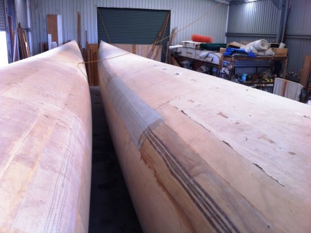
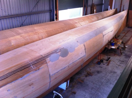
Thanks for the nice pictures! … I am intrigued by them tough, it look like the bottom “half” is developed ply but the upper half also look like another developed ply ? Or is it a curved ply from a one piece scarph ply ?
How was the upper half shape control done ? Just used the bulkheads ?
I am also wondering, between a fractional rig and a Schooner rig with 2 unstayed masts with the same area which one would be in theory more efficient ?
I asked since this cat is even pushing more the multiple unstayed mast vs a bigger fractional rig.
Best Regards,
Luc
Oh, yes, its all happening in a rural hamlet called Eureka, near Hamilton in – as you said – the North Island. I don’t usually point to the dust-coats & latex gloves until at least the 3rd visit of any ‘interested persons’! May make an exception in your case, Kurt…!
Thanks for popping these up, Kurt – must send you a pic of the superfine bows, and maybe a cartoon of the rig..!
I should ‘refine’ the bio detail slightly, if I may; I lead the 60-plus engineer team that developed and bench/enviro-tested the B777 FBW computing hardware, at GEC-Marconi Avionics. Fairer to say Boeing engineers designed the rest of that system, but I will take some credit for our “Primary Flight Computers” ending up over four times more reliable than required. Great plane the B777.. but so weird that flight MH370!
Planning to dress the outside of those hulls (500 sq.m. total area with the two huge ply-tube cross-beams) with 30g/m2 tissue glass. With CM, it only needed ~100hrs on the hulls outside to be ready for the tissue. Thinking maybe stick-on vinyl film instead of paint, straight onto the tissue/epoxy vapour barrier – anyone know the pros/cons?
Beautifull!