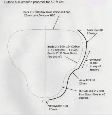
Finally starting to get ahead of the deadlines a bit. Here is the hull laminate drawing by a very famous designer. I consider it completely wrong and I will explain. Every kind of forensic foray like this has teachable moments for all.
First, we surely all agree now that long, slender hulls are most loaded in bending or deflection, depending on the span. Global loads, like a wave at each end, govern over out of plane loads like, water pressure. I first learned about and began to design for global loads after the MACM ’86. This drawing below is a decade later.
We also surely agree that to resist those loads, we must have the most and best laminate fibers oriented along the lines of stress. Zero degree, along the length of the hull for these boats. That is the best way to get a stiff hull.
This drawing has the vast majority of the glass laminate at +-45. That is completely wrong to achieve a stiff hull. It does have carbon on the inside of the hull, which does protect the fragile carbon from crashes. Typically I would complain about rule of mixtures, but the carbon is also +-45 degree orientation here. The best feature of carbon, its very high modulus, is of no use in this arrangement.
And see how this is just as important for the hull deck. For water pressure, the +-45 is fine, but again, the global loads are much greater.
One of the tests I used to do before I knew what to expect was to have my guys jack up one bow of a cat, and see that the other one does. I remember hearing about Larry doing that on Sierra Cloud. The other bow not only came up the same, but took all the blocking with it.
This famous cat deflected 3-1/2″ in the same test. There is no reason to do laminates wrong. Its not a mystery anymore.
Get more details on high pressure laminates from New Mika
Thanks for the considered reply Kurt. I am intrigued by laminates. In Australia we have some famous 80s racing multis with laminates of only 10 oz cloth with poly resin over foam. Needless to say one of these boats is pretty soggy today.
I am intrigued by the idea of global loads being so high compared to other loads. For small multis especially I think that the major load on any laminate could come from dinghies and docks. It certainly seems to be the major cause of damage on small cats under 8 metres in experience. So there will need to be a basic laminate that can handle these high impact loads – something like 600 biax seems standard over 10mm foam as a bare minimum. If we use unis then I would be afraid of splitting the laminate with the dinghy or trailer.
Could you give more details on the paper by Reichards and how to find it?
Cheers
Phil
catch you monday.
Gday Kurt
Good to see something about laminates but I don’t think there is anything wrong with this one here.
First off – we can’t take your premise for granted. It may be that hydrostatic pressure is low but the stress this will put on the hull skin will be greater if the bulkhead spacing is larger – by the square. The fore and aft loading will be pretty much the same no matter the bulkhead spacing. So a hull with fewer bulkheads needs more stiffness and therefore a different laminate.
Also looking at the laminate it looks pretty standard engineering. If we accept your premise that global loads are greatest then the deck or keel will be in compression/ tension. Hence the biaxial laminate with 50% of the laminate in the loaded direction. As the core is foam you need some axial laminate so 90 degrees is fine. Also both the keel and deck will be subject to impacts from winch handles or shells so extra bulk is needed.
So the hull sides are part of a shear web to global loads. A shear web is loaded in shear and therefore should have a plus and minus 45 degree laminate – all normal engineering. If you were to design a laminate with only fore and aft uni then the hull sides could not act as a shear web and the laminate would fail along the resin glue lines. I would say that you use +-45 db on your crossbeam shear webs too.
cheers
Phil
not quite. I suggest you read Prof. Reichards paper on catamaran structure. Failing that you can run beam load situations with hull as beam easily using first principles. And also run hydro simulations. Easy to see which is higher load. If you have a source declaring that long, slender globally loaded shapes do not need mostly 0 degree fibers, let me know about it. Otherwise keep checking in. I don’t just make this stuff up.
Longer span between bulkheads does decrease resisting loads from both hydro and buckling from global loads.
If I may, in composites there is no standard engineering. The engineering must be tailored to the loads.
You forget the hull gets global loads highest from the side; falling off a wave onto a bow for example.
Shear does not govern so you design for the governing loads and if done right, the shear is already staisfied. Remember that your singular shear web must also contribute to bending strength to be efficient.
Flex test result sounds like weak cross beams and house, which to me sounds like a recipe for an even bigger catastrophic event. Total breakup not just broke off your nose!
Thanks for bringing it up. I was thinking about doing something similar: multiple cores, carbon inside and some kind of multi-axial roving. One of the downfall of many older boats is loss of strength and transmission problems associated with it.
On my former boat, the propeller shaft would misalign about an inch between full load and light load making it a pain and major expense. I say at least 30% of the boats have this problem more or less.
ps: One of the factors that led to the abandonment of the Gunboat 55 Rainmaker was all the broken glass everywhere. (nicely lubricated with hydraulic fluid from the mast control lines) Glass! Must be several hundred pounds of it in that gazebo.
Should have blocked out that London address. Too much of a tell for us forensic ghostbusters.