It looks like I might have made a big mistake buying these switches. They don’t work, and Adafruit, the company in New York, has a policy of not allowing any calls nor emails either way on anything.
https://www.adafruit.com/product/1476
A switch should be pretty simple; a hot and a ground in, and the same out. Switch shows negative on one side and plus on the other. Simple. I spent hours trying every possible combination. Nothing. The lights worked great when I put the connectors together without a switch. The switches had no instructions.
Online it says “ The body is a black plastic with the LED built inside. There are two contacts for the button and two contacts for the LED, one marked + and one -. The forward voltage of the LED is about 3V so connect a 220 to 1000 ohm resistor in series just as you would with any other LED to your 3V or higher power supply. “ I wish I could as them what that means. It takes two contacts in and two out to be a switch in the universe I know.
Also the spade terminals are non standard size and are too fragile to tolerate crimped standard female terminals.
I would have been happy to pay much more to get the working version. If there was anyone who I could tell me what to do. What am I missing?
The pisser is they are so cool, if they worked.
Hi!
If you have fed the LED with 12 v direct you probably burnt the LED. A single 3v LED which might draw 30 mA needs a 330 ohm resistor. http://led.linear1.org/1led.wiz
I love your designs!
Best regards from Sweden
Jens
I found and bought resistors and a solder kit. I may be good now. I still wish it were plug and play.
(or two resistors or whatever). If it got too much current at some point there is a chance it overheated and let the magic smoke out (which turns it from an LED to a DED Dark Emitting Diode)
And you are using the latching switch to turn on/off a 12v DC circuit I assume? In that case if the LED needs 20ma then a 400ma resistor should help keep the LED from getting too much current (like it would get if you just hooked it directly to the 12V). If it needs more than 20ma then a smaller resistor could work
Is it a momentary switch (i.e. it only connects the two switch wires while the button is pressed)?
latching
Hi Kurt,
Like Lars said this is a single switch and a single LED.
You have to treat it as two seperate things in one housing.
The switch doesn’t affect the LED automatically.
If you switch the hot/+ , you can ad the LED (and a resistor in series) at the output of the switch :
connect the “+” of the LED terminal with the output of the switch, and the ” – ” labeled connector via a resistor to your ground/the batterie’s minus pole.
Would be simpler to draw but I cannot attach a drawing.
Regards, Hans
thanks,
I have no idea of a wiring diagram that would work on that. No idea what voltage the LED needs, and no idea how to pick a resistor, if that’s what I need.
Thankful if you have any information or drawings. khughes@multihulldesigns.com or text 206 719 4893
Kurt
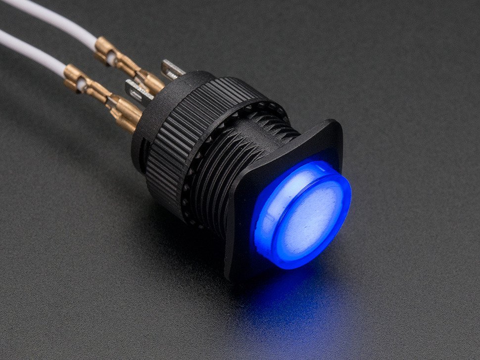
the pair closer to the edge is the switch, the other pair is for the led. If you applied too much power, the led is dead.
Led is polarity sensitive, which is why it’s marked…
The picture shows the pins needed to light the led, the led is generally meant to be controlled by a microcontroller, that’s why both leads have pins. If you use it for the switched power, you will have to ensure the voltage is correct.
It does look like a cool switch. Hopefully it’s not just a case of you getting the sole defective one in the batch, that’s always so frustrating. Have you tried an ohm meter to figure out what’s connecting to what before and after a press of the button?
Found your site a while back after spotting the Eco Trekker picture online – what a great design. I’ll send an email with a concept I’ve been kicking around for a few years, and perhaps can be easily derived from your design, as the Tri-Trawler is a bit too large for the space I have.
Thanks – Lars
Perhaps the + and – connections just for the led which requires a specific voltage and polarity, and two unlabeled connections for switching the hot side (at whatever voltage), no switching of the ground wires that are tied together outside of the switch at all times. Sounds like an automotive style single pole switch.
I got that about the ground wires. I do understand that the switching is the bigger tabs. No combination of anything lights up the switch so far. I did post on their blog and I have not had time to look yet. Some instructions would be expected.